
Measuring probes
Let the probe find the datum
CNC Probing infrared measuring probe — 1 micron repeatability
Finding the datum by hand after clamping a part takes time and leaves an error source that depends on the operator. A measuring probe does this automatically: it locates the part, writes the work coordinates and verifies the dimension before cutting begins.
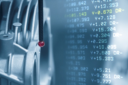
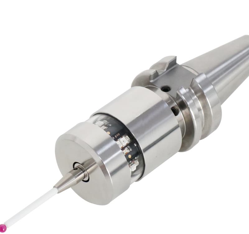
The CNC Probing infrared measuring probe is a unit that mounts in the spindle taper. Before machining it establishes the coordinates of the workpiece and removes incoming material error. During and after machining it takes dimensions such as flatness, distance, angle and bore diameter. Quality control is thereby moved inside the machine; scrap falls and the machine is not stopped for measurement.
Kinematic resistive design
The probe works on the kinematic resistive principle, proven in the industry over a long period. The stylus sits on three ball seats under spring force and a current passes through those seats. When the stylus touches a surface the contact area between the balls reduces, resistance rises and the system produces a trigger signal. When contact is released the spring reseats the stylus.
The balls and rods go through a special process that provides a trigger life of 10 million operations. In addition, a micro-oscillation self-reset design eliminates the unstable repeatability often seen in probes of this type. With a standard 50 mm stylus at 600 mm/min, unidirectional repeatability is 1 micron.
Uninterrupted signal transmission
Signal transmission uses coded optical communication; transmission is stable, response is fast and no signal is lost. A dual-channel design with remote frequency change solves the problem of infrared probes interfering with one another in the same workshop. Transmission is 360 degrees around the probe axis and the operating range is 5 metres.
Long battery life
The probe uses multi-threshold power consumption control. Consumption has been reduced through improved chip and circuit design. Battery life is more than 360 days in continuous use, more than 540 days at five per cent use and more than 600 days on standby. The batteries are standard LS14250 lithium cells and are easy to source.
Magnetic base for easy mounting
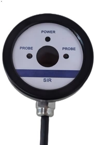
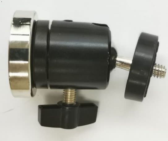
Mounting the receiver usually requires drilling holes in the machine. The CNC Probing receiver is supplied with a magnetic base; the receiver is attached to the base and the base to the sheet metal of the machine. Installation takes minutes, no holes are drilled and the receiver can be moved elsewhere if needed.
| Model | SOMP40 |
|---|---|
| Unidirectional repeatability | 1 µm (2σ) (50 mm stylus, 600 mm/min) |
| Sensing directions | ±X, ±Y, +Z |
| Trigger force | XY: 0.4 – 0.8 N Z: 4.0 N |
| Over-travel protection | XY: ±15° Z: 6.35 mm |
| Signal transmission | Infrared, pulse triggered |
| Operating range | 5m |
| Transmission angle | 360° around the probe axis |
| Trigger life | More than 10 million |
| Weight | 280 g (excluding shank, with batteries) |
| Battery | 2 × lithium LS14250 |
| Battery life | Standby > 600 days 5% use > 540 days Continuous > 360 days |
| Sealing | IP68 |
| Operating temperature | 0 – 60 °C |
| Certification | ISO 9001 |
Styli
The smallest part that decides the measurement
CNC Probing styli — selection guide
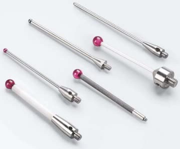
The stylus is the only part of the probe that touches the workpiece. If the roundness of the ball is poor, if the stem bends or if the thread tolerance is large, the measurement is corrupted however precise the probe is. A wrongly chosen stylus can reduce measuring accuracy by as much as ten per cent.
Straight styli
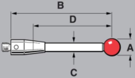
This is the most common type and is used for the majority of measurements. Stems may be shouldered or tapered; where the workpiece is easy to reach, a tapered stem gives higher rigidity. Ball materials include ruby, silicon nitride, zirconia, ceramic and tungsten carbide. Stem and holder materials are titanium, tungsten carbide, stainless steel, ceramic and carbon fibre.
Cylinder styli
On sheet metal, pressed components and thin-walled workpieces, proper contact cannot be guaranteed with a ball stylus; a cylinder stylus is used instead. Thread profiles can also be probed and the centres of tapped holes located with this type. Ball-ended cylinder styli allow datuming in all three of the X, Y and Z directions, so surface inspection can be carried out as well.
Extensions
Extensions are used for very deep pockets and bores, or for points that are hard to reach. Every joint adds a point of deflection, so extensions are best avoided unless they are needed.
Styli are produced in standard and custom sizes.
Choosing the material
Tungsten carbide gives high rigidity and is preferred for small stem diameters and shouldered styli. With large stem diameters and long styli, however, its weight needs attention. Ceramic is light and is therefore used for long styli; it is thermally stable and provides break protection in machine tool applications. Steel gives high rigidity in standard applications where weight is not an issue. Carbon fibre weighs about one fifth of tungsten carbide and is the best choice for very long styli and for production environments needing thermal stability.
Three rules when choosing a stylus
| Material | Weight · Rigidity · Where it is used |
|---|---|
| Tungsten carbide | Heavy · Very high · Small stem diameters and shouldered styli; most standard applications |
| Ceramic | Light · Medium – high · Long styli; thermal stability and break protection on the machine |
| Steel | Heavy · High · Standard applications where weight is not an issue |
| Carbon fibre | Very light · Medium · Very long styli; machines with high vibration |
Ball material is chosen separately: ruby, silicon nitride, zirconia, ceramic or tungsten carbide. Holder and stem materials are titanium, tungsten carbide, stainless steel, ceramic and carbon fibre.
Probe tool holders
The part that seats the probe in the spindle
CNC Probing tool holders — BT, HSK, SK and CAT
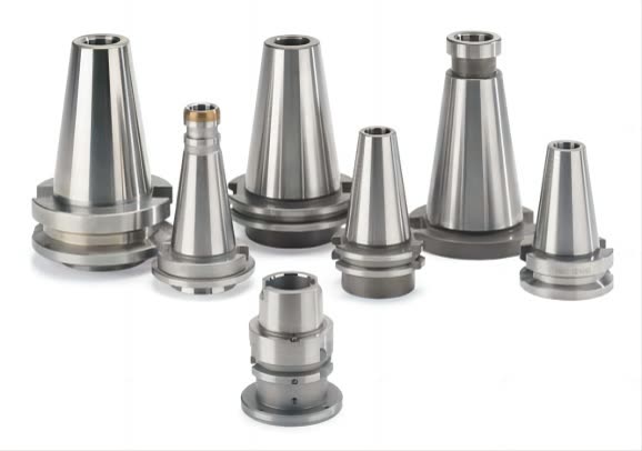
The probe is mounted in the spindle taper with a tool holder. The job of the holder is not only to hold: it seats the probe in line with the spindle axis. If the holder is chosen wrongly, or if centring is not carried out, every measurement carries a constant deviation however precise the probe is.
Selection in three steps
Two pieces of information are enough
Choosing the right holder requires two things to be known: the spindle taper of the machine and the body diameter of the probe. The taper is read from the machine model. The model code combines these two.
Four taper families
The range covers BT, HSK, SK and CAT tapers. BT and SK series are common on machining centres of Japanese and European origin, the CAT series on machines of American origin, and the HSK series on high-speed and precision machining centres. Both E and A type bodies are available in the HSK family.
Pull stud and adjusting screws included
Every holder is delivered together with its pull stud and centring adjustment screws. No separate parts need to be ordered. The adjusting screws bring the stylus tip in line with the spindle axis; this adjustment is made once when the probe is first fitted.
| BT series | CP-BT30-D11.2 CP-BT30-D20 CP-BT40-D11.2 CP-BT40-D20 CP-BT50-D11.2 CP-BT50-D20 |
|---|---|
| HSK series | CP-HSK25E-D11.2 CP-HSK32E-D11.2 CP-HSK40E-D11.2 CP-HSK50E-D11.2 CP-HSK63E-D11.2 CP-HSK63A-D20 CP-HSK100A-D20 |
| SK series | CP-SK30-D11.2 CP-SK40-D11.2 CP-SK50-D11.2 CP-SK40-D20 CP-SK50-D20 |
| CAT series | CP-CAT30-D11.2 CP-CAT40-D11.2 CP-CAT50-D11.2 CP-CAT50-D20 |
The repeatability figure is that of the device itself; the positioning error of the machine is not included. Accuracy achieved in the field depends on how the device and the machine behave together.