CNC PROBING · Accuracy starts at the machine Log in / Sign up
TR RU 中文
CNC PROBING
Home › CNC Probing

Measurement software

Measure your workpiece on your CNC machine

Taking a part off the machine to measure it and waiting in line at the inspection room is one of the most expensive habits in manufacturing. Once the part comes off, the set-up reference is lost; even when an error is found, the part has to be re-clamped and re-datumed to correct it. Measuring on the machine removes this loop.

Because the part stays clamped, the result comes within a few minutes and any correction is made in the same set-up. The machine does not wait for word from the inspection room. Scrap and rework go down, and the measurement record is produced as part of the job itself.

CNC Probing is software that lets the workpiece be measured on the machine tool. The measurement is taken where the part is machined and in the same set-up. Measurement points are selected on the model of the part, and the code that will run on the machine is generated by the software. The user does not have to write macros or edit Gcode (tool path).

CNC Probing supports the probe brands commonly used in the industry.

The CNC Probing main screen
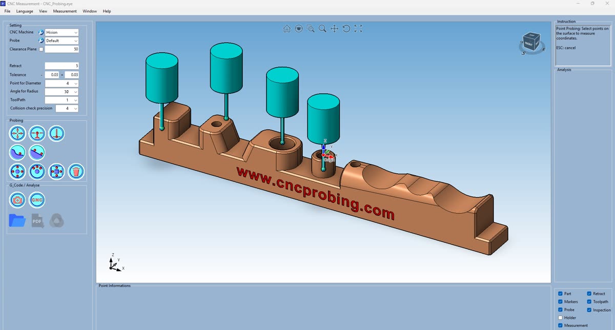
The CNC Probing main screen. Measurement types on the left, the part in the centre in 3D, settings in one panel.

An interface that is easy to use

Measurement types sit as icons in the left panel and the part appears in the centre of the screen in 3D. Tolerance, retract distance, the number of points for a diameter and the collision check precision are gathered in one place on the same screen. A measurement point is picked on the part itself and the chosen point is marked on screen straight away. The user works while seeing what is being done.

CNC machine library

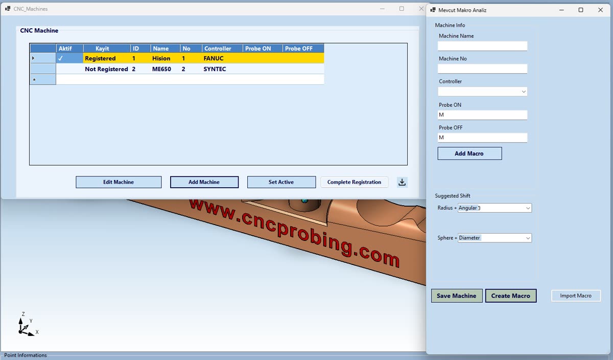
The software keeps its own machine library. Every machine tool in the shop is defined as a separate record, edited, and set as the active machine when needed. A separate macro is produced for each machine, so records do not get mixed up in a shop running several machines.

The software resolves macro conflicts

Macros are already stored in the machine control. If a macro added from outside uses the same number, a conflict arises. CNC Probing does not leave this to the user: it analyses the macros found on the machine and produces a macro specific to that machine which does not clash with the existing ones. The process is automatic. There is no macro number to choose, no macro to write, and no technical staff to call in for it.

Probe library and instant 3D

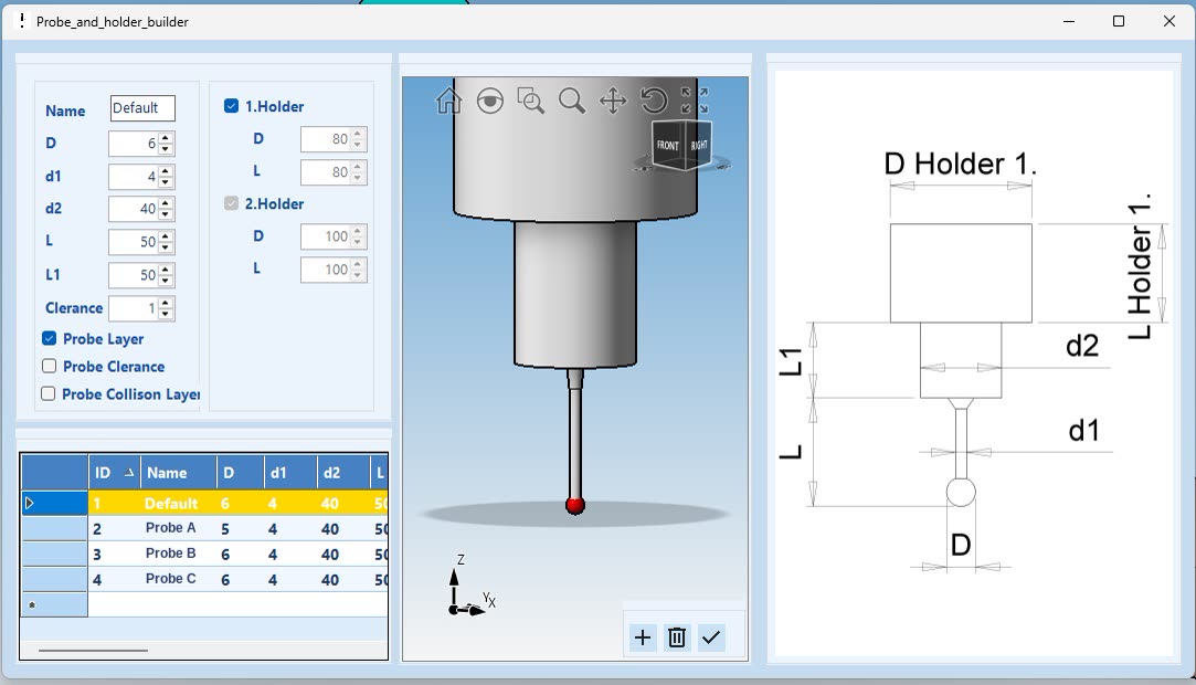
Probes are kept in a library as well. You can select a stored probe or define your own: stylus diameter, stem diameter, body diameter, lengths and holder dimensions are entered. As the values are entered, the probe and the holder are built on screen in 3D at the same time, with a dimensioned diagram beside them.

The CNC machine library and macro analysis
The CNC machine library and macro analysis. Each machine tool is a separate record.
The probe builder
The probe builder. The model appears in 3D as the dimensions are entered.

Measurement software

Preparing the measurement

Placing the model, choosing what to measure, knowing the probe

The accuracy of a measurement is decided before any code reaches the machine. Is the model sitting in the right place? Have the right features been selected? How does the probe actually behave? These are questions for the preparation stage, answered at the screen rather than at the machine. CNC Probing brings all three together on one screen.

Setting the model on the machine datum

A STEP or IGES file taken from CAD/CAM software rarely arrives on the machine datum you want; the part is shifted, rotated, or its zero sits in another corner. It is a small matter, but measurement cannot begin until it is settled, because every measurement point will be worked out from this reference.

The software brings the model in and offers several ways to put the datum where it belongs. One of them builds a box around the part and offers a zero at every corner; the user picks the one they want and the part moves to it. Alignment on a plane, an edge or a point is also possible.

When the datum changes, probing points created earlier are deleted. This is deliberate: those points were worked out from a different reference, and keeping them would quietly produce a wrong result. Datum first, measurement after.

Measurement modes

Point probing, angled surface, inside and outside circle, inside and outside radius, inside and outside pocket, and rectangular surface probing. When a mode is selected, the surfaces that suit it are highlighted on the model; the user only clicks. The software tells a bore from a boss on its own. In point probing every surface except downward-facing ones can be selected, with as many points as wanted.

When measuring a bore or a boss, the number of points the probe touches is chosen: four or eight. More points make the measurement more dependable but lengthen the cycle. In series production four is usually enough; if the part is tight or the roundness of the bore is in doubt, it goes to eight. The choice belongs to the user; the software does not impose one.

The settings in one panel

The values that shape a measurement are not hunted for in scattered menus; they sit in the same panel. Retract sets the distance between the probe and the workpiece. The plus and minus tolerance of the point being measured goes into Tolerance. Point for Diameter sets how many points are taken in a diameter measurement, and Angle for Radius the angle used in angular measurements. ToolPath selects the tool path number. All of it visible, all of it in one place.

On three, four and five axes

The software runs on 3-axis vertical and horizontal machining centres, on 4-axis machines with a rotary table and on 5-axis machines. The more axes there are, the more directions the probe can reach the workpiece from; on 5-axis machines surfaces at different angles can be measured in a single set-up. Measuring accuracy is in the range of 0.001 – 0.005 mm; that figure is reached together with the positioning accuracy of the machine.

Instruction panelIt writes out, step by step, what to do at every stage of every operation. The user does not get lost in the program and learns unaided.
Show / hideThe part, the probe body, the probe ball and the tool paths are switched on and off separately. There is no need to work on a crowded screen.
The control is left aloneNothing is changed in the machine control unit; existing programs and settings stay as they are.
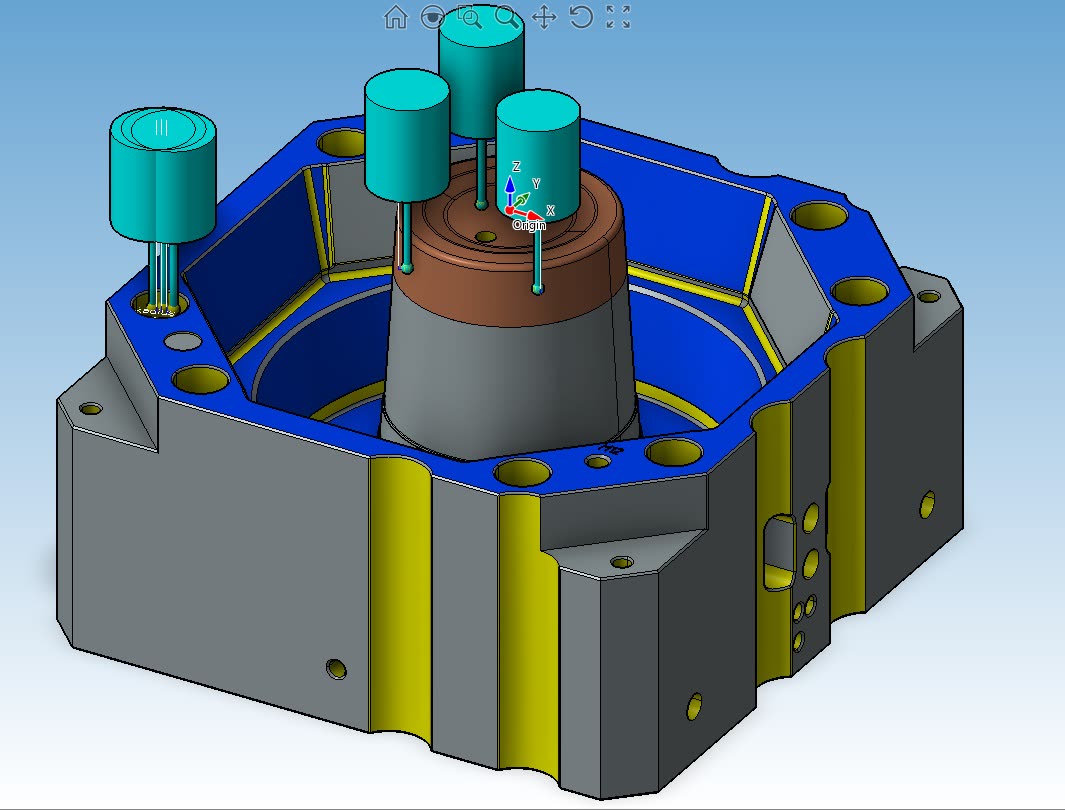
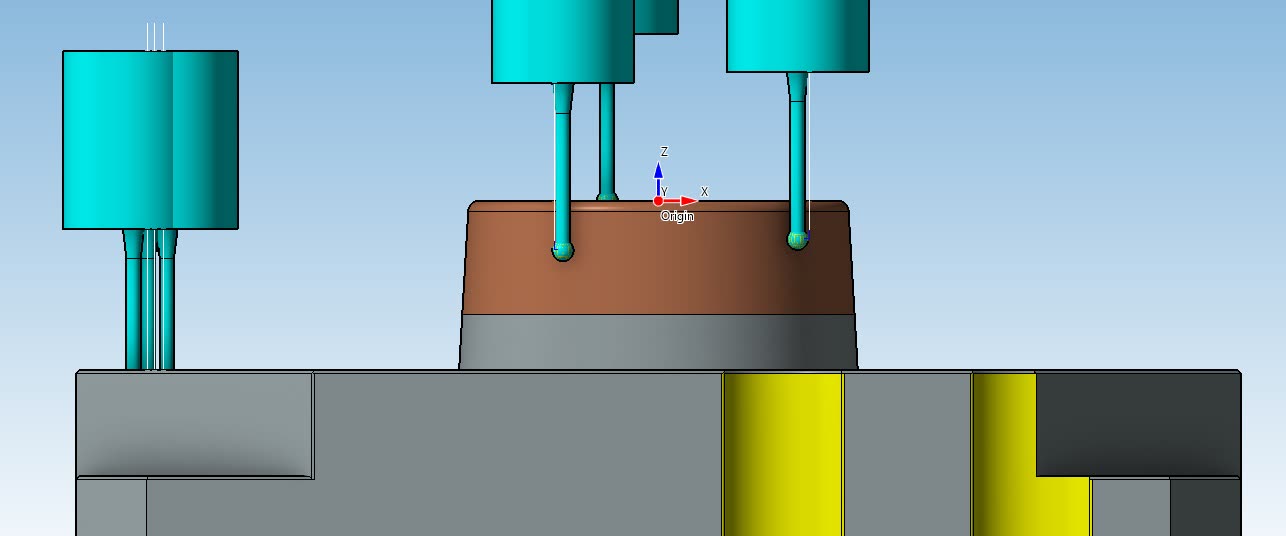
Probing points are marked on the model
Probing points are marked on the model; probe and holder are shown.

Measurement software

Before the code reaches the machine

Collision checking, animation and machine-specific Gcode (tool path)

A probe is an expensive instrument, and when it breaks it does not only cost its own price: the machine stops, the job is delayed, a replacement is waited for. So CNC Probing puts the path it produces through three stages before sending it to the machine. A safe height is set, collision is checked, and the path is watched on screen.

Safe height

Clearance Plane sets the height at which the probe travels from one measuring point to the next. The probe moves above this plane at speed and comes down only once it is over the measuring point. Clamps, vice jaws and the high areas of the part are thus kept out of the path.

The value can be entered by hand; the software also finds the highest point of the model and proposes a safe zone itself. One wrongly entered height costs a broken probe, which is why this field is visible from the start.

Collision checking

What breaks a probe is usually not the measurement itself. If the stylus touches something outside the measurement, or the probe body strikes a clamp, the probe breaks or is damaged. CNC Probing runs a collision check for every measuring point as it is selected; if a collision is found, probing is not started and the user is warned.

The check takes in not only the stylus but the body and the holder as well. The dimensions entered in the probe library are there for exactly this: the software cannot call a path safe without knowing how much room each part takes up.

The software sets the approach angle

To measure a point correctly the probe has to approach the surface at a right angle. On sloped and curved surfaces that angle changes at every point; working it out by hand takes time and leaves room for error. CNC Probing analyses the CAD geometry, calculates the surface normal at each measuring point and decides for itself which direction the probe comes from. The user enters no angles and does no trial and error.

Watching the path on screen first

The path that has been produced is played back as an animation in three dimensions. The probe moves step by step, and at every move the X, Y and Z coordinates, the feed and the retract value appear on screen. The animation can be wound forwards and back and stopped at any point.

This takes the place of the dry run on the machine. The usual method is to send the program to the machine, drop the feed to ten per cent and watch the path with a hand on the stop button. Watching it on screen saves both the machine time and that risk.

The post processor is inside the software

For a tool path produced by CAM software to run on the machine, it has to be translated into code the machine understands. A post processor does that translation, and it can differ according to the CNC machine's control unit.

CNC Probing carries its post processor within itself. It produces Gcode (tool path) suited to the control of the machine chosen in the machine library; the header information, the safety lines and the cycle format are written for that machine. There is no need to obtain a post processor separately; the user takes the code, transfers it to the machine and runs it.

Results appear without waiting

Measurement results coming back from the machine are loaded into the software and appear on screen at once. Values inside tolerance and those outside it are shown together on a colour scale; how far each point has deviated is read at a glance. There is no report to wait for once measuring is over.

Results are saved as PDF; a screenshot can be added to the report as well. Because the Q-DAS / AQDEF format is supported, measurements pass straight into the quality system.

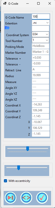
Gcode (tool path) formCoordinat System (G54) · Tool Number · Probing Mode · Marker Number · Tolerance + / − · Retract Line · Radius · Measure · Angle XY / YZ / XZ · X, Y, Z coordinates · With eccentricity. Header information, safety lines and the checksum are written as well; no line has to be added to the code by hand.
One form to the machineEvery probing operation carried out is turned into Gcode (tool path) through a single form and transferred to the machine.
Set up with one macroSetting up is done with a single macro; no separate post processor has to be bought.
The report is part of the jobThe measurement record is not compiled afterwards; when the cycle ends the report is ready.
Tool path animation
Tool path animation. The probe moves step by step and the coordinates appear on screen.
The Gcode (tool path) panel

Home