
Tool control systems
Catching a broken tool in cycle
CNC Probing non-contact laser tool setters
SNC non-contact laser tool setting system — SNC56 · SNC86 · SNC168
The most expensive failure in a machine shop is a broken tool noticed too late. A machine that does not stop at the moment of breakage keeps producing bad parts.
In series production it is usually impossible to establish afterwards in which cycle a tool broke and why. The cost is not one scrap part: rework labour, machine standing time, a slipped delivery date and suspect parts going to the customer all count as well. A control system that catches breakage within the cycle removes all of these.
No contact
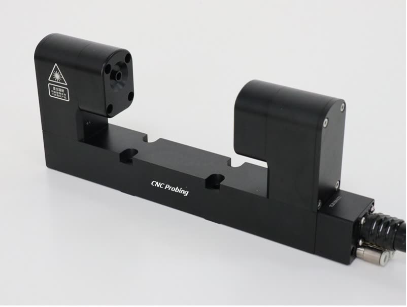
The CNC Probing laser tool setter measures the tool without touching it. Transmitter and receiver face each other; when the tool enters the beam path the light reaching the receiver falls, and below the set threshold the system triggers. The axis position at that moment gives the true tool length; diameter is measured the same way. With no contact, even the smallest and most fragile cutters are checked without collision risk. A single check takes a few seconds.
Measurement at working speed
The most important feature of this system is that measurement is taken while the tool turns at its own working speed. The result therefore includes not only the geometry of the cutter but also the deviation coming from the spindle and the tool holder. The dimension is obtained under real cutting conditions and can be corrected directly. A separate tool presetter is not needed; measured values are written automatically into the tool offset table.
Control inside the cycle
The check is placed inside the machining cycle. The tool is measured before it starts work and again after it finishes. The difference shows the wear on the cutter; if it is outside the expected value the tool has broken. The cycle is then stopped or a backup tool is called. The decision does not wait for the operator. Single-edge and form checking run in the same cycle.
Built for shop-floor conditions
The optical surfaces are protected behind a pneumatic shutter that opens only during measurement; with the shutter closed, coolant and swarf cannot reach the lens. During measurement a curtain of clean compressed air continues to protect the optics. An air blast unit clears swarf and coolant from the tool immediately before measuring, which prevents false triggering. An anti-drip design and machine temperature compensation are standard.
The laser diode is switched on only for the duration of the measuring cycle. This reduces heating and power loss and extends diode life considerably. The system is connected to the CNC control unit through three enable lines.
System components
The system consists of four main parts: laser transmitter, receiver, mounting plate and air blast module. The transmitter uses a spotting laser; the beam diameter is small and the centre of the light source is easy to adjust, which makes installation and alignment of the beam path easier. The air path is built into the housing and is normally open, so the beam path stays clean.
Interface unit
The interface unit processes the signal from the laser system, converts it into an output the CNC control unit can read and passes it to the signal input of the control unit. The terminals are labelled individually for supply, laser on/off, pulse mode and skip inputs. Wiring must follow the user manual; incorrect connection can cause measurement error and hardware damage.
Three measuring apertures
Three measuring apertures are offered: 56, 86 and 168 mm between transmitter and receiver, covering machines from small vertical machining centres to large-capacity ones. The connection is hard-wired; standard cable length is 8 metres and can be changed on request. The unit is delivered with the interface unit and the compressed air unit.
It covers three models: SNC56, SNC86 and SNC168. The models differ in measuring aperture; the operating principle and the installation procedure are the same.
| Measuring aperture | 56 / 86 / 168 mm |
|---|---|
| Repeatability | ±1 µm (2σ) |
| Connection | Hard-wired, 8 m standard |
| Measuring functions | Tool length, tool diameter, broken tool detection, single-edge and form check |
| Protection | Pneumatic shutter, clean air curtain, anti-drip |
| Compensation | Machine temperature compensation |
| Warranty | 1 year |
Technical data and measuring functions
CNC Probing non-contact laser tool setter
Four measuring functions
| Parameter | Value |
|---|---|
| Principal application | High-precision, high-speed non-contact tool setting and broken tool detection on vertical and horizontal machining centres of all sizes, multi-tasking machines and gantry machining centres |
| Beam alignment | Supplied with an adjustable mounting plate on the underside |
| Connection (to interface) | Hard-wired system; cable at the end of the unit |
| Sealing | IPX8 |
| Typical repeatability | ±0.1 µm (2σ) |
| Repeatability | ±1 µm (2σ) |
| Minimum tool size | Ø0.1 mm or larger |
| Maximum tool size | 86 mm |
| Minimum tool for breakage detection | Ø0.1 mm or larger |
| Power | 100 mA @ 24 V |
| Output signal | Voltage-free solid state relay (SSR); each relay may be normally open. Max. current 50 mA, max. voltage ±50 V |
| Storage temperature | -10 °C … 50 °C |
| Operating temperature | 5 °C … 50 °C |
| Life | Tested to more than 1 million on/off cycles |
| Pneumatic supply | 4 mm air pipe; 6.0 bar maximum, 3.0 bar minimum |
| Cable | Ø6.0 mm × 8 m; two twisted pairs, two individual cores plus screen, each core 18 × 0.1 mm insulated |
| Mounting | M10 |
On / off characteristics
The laser system is switched on by the CNC control unit through three enable lines. The transmitter signal turns the laser beam on or off; to minimise heating and power loss the diode stays on only during the measuring cycle. When the receiver is enabled, the operating mode of the protective shutter is determined by the corresponding measuring cycle. Once transmitter and receiver are enabled, if the light reaching the receiver is at least 75 per cent of the maximum value, the output signal of the system is used as the trigger signal.
Dimensions
Dimensions are in millimetres. Beam aperture 86 mm, beam height 69 mm, body length 208 mm. Four Ø5.4 mm holes for mounting; hole spacing 60 and 20 mm.
The repeatability figure is that of the device itself; the positioning error of the machine is not included. Accuracy achieved in the field depends on how the device and the machine behave together.